Architecture
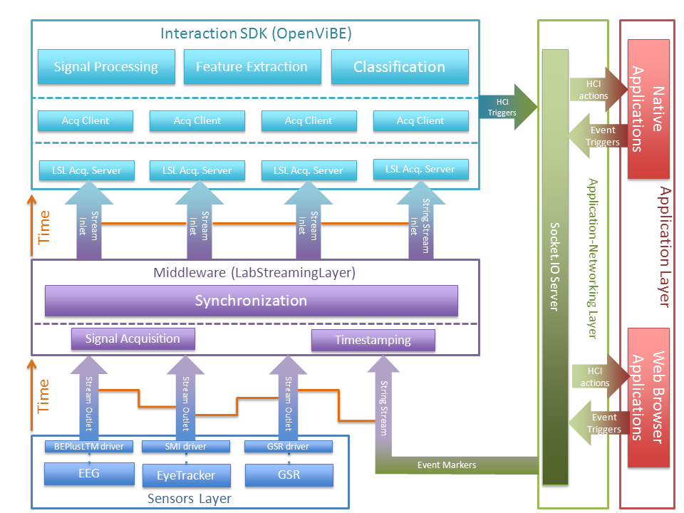
The first Layer is the Sensors Layer that has the role of capturing the signal from the sensor devices in order to push it further up in our architecture. Apart from the actual hardware (i.e. EEG recorder, Eye-tracker and GSR sensor), among the Modules of the Sensors Layer we also classify the Drivers (one for each hardware device) that are necessary to make the generated signals available for MAMEM’s Middleware. These Drivers have been built using the SDK of each device so as to provide the signals in a structure suitable for our Middleware. This structure is essential the Stream Outlet Interface which specifies how to structure a stream so as to be compatible with MAMEM’s middleware. The Stream Outlet Interface is the only Output Interface of the Sensors Layer, whereas as Input Interface we may consider the output of the low-level drivers that typically come along with the sensor devices.
The second Layer is the Middleware. The role of this Layer is to act as the mediator between the sensor devices and the rest of MAMEM’s architecture. In other words, as long as a new sensor device can comply with the Input Interface of this middleware, the rest of the system should operate seamlessly. In the proposed architecture, the framework named LabStreamingLayer has been chosen to serve as MAMEM’s middleware. The Middleware consist of three Modules, namely Signal Acquisition, Timestamping and Synchronization. Signal Acquisition is the module responsible for receiving the signals from the Sensors Layer. The role of Timestamping is to add timestamps on the received signals. Finally, the most important Module of our Middleware is the Synchronisation Module that takes care of synchronizing the (originally de-synchronized) signals based on their timestamps (as well as other sensor-specific delays). As a result, the signals can be pushed further-up in MAMEM’s architecture in a synchronized mode. There are two input and two output interfaces associated with the Middleware. The input interfaces are the Stream Outlet and the String Stream Outlet. The first refers to the structure that should be followed by the signal coming from the Sensors Layer. The second is a specific type of interface that allows our Middleware to receive strings at irregular frequencies, which are typically used to mark the beginning or the end of an event. In our architecture, we foresee the use of this interface as the means for the end-user application to communicate the point in time where a certain action or process should be initiated in the back-end. Finally, the output interfaces consists of the Synched Stream Inlet and Synched String Stream Inlet, which specify the structure of the signal and string streams that should be followed by another layer in order to receive information from the Middleware. The main difference compared to the signals received by the Middleware is that on its output the signals are synchronized.
The third Layer in our architecture is the Interaction SDK. The role of this Layer is threefold: a) communicate transparently with the Middleware, so as to receive the synchronized signals, b) implement an extensive list of processes and methods for translating the bio-signal into triggers for the HCI, and c) communicate these triggers with the front-end of our system. In the proposed architecture, the framework named OpenViBE has been selected to serve as the back-bone of MAMEM’s Interaction SDK. OpenViBE consists of various different Modules. First, we should refer to the Acquisition Server which is the module responsible for receiving the Signal and String Inlets from our Middleware. This module should be instantiated as many times as the number of existing signal and string streams and ensures that these streams will made available to the processes and methods implemented within OpenViBE. Actually, in order to do this, all instantiated Acquisition Servers should be paired with an instance of an Acquisition Client, which is the other module classified under the Interaction SDK Layer. This module ensures that the incoming signal and string streams will be made available to the processing Modules of OpenViBE, such as Signal Processing, Feature Extraction and Classification. Finally, in terms of the associated interfaces we can distinguish between External Input Interfaces, Internal Input Interfaces and Output Interfaces. In the External Input Interface we can classify the Signal and String Stream Inlet, which is the structure of the streams that comes out of the Middleware Layer. In the Internal Input Interfaces (these do not appear in the figure to maintain the clarity of the diagram) we can classify the Signal Acquisition Server that is used to pass the streams from the Acquisition Server to the Acquisition Client and the Signal Acquisition Client that is used to pass the signal from the Acquisition Client to the Processing Modules. Finally, in the Output Interfaces we classify the HCI Triggers Interface, which is essentially the structure of the messages that are communicated from the Interaction SDK to the Application-Network Layer and subsequently to the Application Layer in order for certain HCI commands to be executed in the front-end application
The fourth Layer in our architecture is the Applications-Network Layer. The role of this Layer is to handle the communication between the Interaction SDK and the front-end Application Layer. In particular, the Applications-Network Layer consists of one module namely, Socket.IO Server, which is intended to implement a server that will be able to communicate with a number of clients through network sockets. There are four different interfaces associated with this Layer. Among the Input Interfaces we can classify the Event Triggers and the HCI Triggers. The Event Triggers Interface is the structure of the messages that should be communicated by the end-user application to inform the back-end system that a certain task has started (e.g. the process of presenting the visual stimuli to the user has started and the back-end system should decide which of the flickering boxes is selected by the user based on his/her brain electrical signals). These messages will be subsequently formulated in a String Stream Outlet that will be passed on to the Middleware. The HCI Triggers Interface is the structure of the messages that should be communicated from the Interaction SDK to the Applications-Network Layer in order to pass on the information about the output of a certain signal analysis tasks (e.g. continuing from the previous example, these messages should inform the Applications-Network Layer that the flickering box that has been selected by the user is the one on the upper-left part of the screen). Finally, the output interfaces of the Applications-Network Layer, consists of: a) the HCI Actions Interface, which specifies the structure of the information that will be received by the native or web browser application and be translated in commands for the interface; and b) The String Stream Outlet Interface, which takes care of translating the event triggers into a string stream outlet suitable for our Middleware.
The fifth and final layer of our architecture is the Application Layer. This Layer is used to represent the end-user applications that will be operated through the users’ eyes and mind. It consists of two modules titled as Native Application and Web Browser Application that are used as containers for all different types of applications that will be developed in MAMEM. The Interfaces in this Layer are essentially identical with the ones presented in the Applications-Network Layer where the input/output property is reversed. Thus, the HCI Action Interface is now the input interface that determines the structure of the messages that will be translated into HCI commands, and the Event Triggers Interface is the structure of the messages that are used to mark the begin/end of a certain HCI-related task.